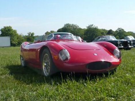
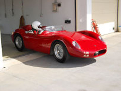
O.S.C.A. spells Maserati
Officine Specializzate Costruzioni Automobili - Fratelli Maserati SpA (established 1947 in Bologna, discontinued 1967) was an Italian brand of sports car automobiles, usually abbreviated to O.S.C.A., OSCA or Osca.
It was founded by Ernesto (engineering manager) and his two brothers Ettore, and Bindo Maserati (operations managers). The brothers left Maserati after their ten-year contract with Adolfo Orsi had terminated. Ten years earlier, in 1937, the remaining Maserati brothers had sold their shares in the company to the Orsi family, who, in 1940, had relocated the company headquarters to their hometown of Modena, where it remains to this day. The new workshop for O.S.C.A. was established at San Lazzaro di Saveno outside Bologna,[1] where Maserati was originally made 1926 to 1940. Their basic business goal was to develop an automobile to compete in the 1100Â cc racing class.
O.S.C.A.'s first automobile was the MT4, for Maserati Tipo 4 cilindri. The 1092Â cc engine (72Â bhp at 6000Â rpm) had a FIAT-derived block, alloy top, and the coach was built as a two-seater barchetta. The MT4 first raced in 1948 at the Pescara Circuit and the Grand Prix of Naples, where it was driven to a win by Luigi Villoresi. The engine was modified to 1342Â cc form (with 90Â bhp at 5500Â rpm) in 1949.[2] In 1950, a new DOHC (MT4-2AD) raised power (to a maximum of 100Â bhp at 6300Â rpm), and until 1953 the engine would be enlarged to a maximum of 1453Â cc (110Â bhp at 6200Â rpm). A twin spark with 1491Â cc (120Â bhp at 6300Â rpm) was later used in the O.S.C.A. TN of 1955.
Mostly these automobiles were barchettas, but a few were built as more luxurious berlinetta coaches by Pietro Frua, Michelotti, and Vignale. A Vignale was run in the 1500Â cc class at the 1953 24 Hours of Le Mans. The 1954 12 Hours of Sebring was won by drivers, Stirling Moss and Bill Lloyd, in an O.S.C.A. MT4 [1] as part of the Briggs Cunningham Team.[3] From 1951 to 1962, automobiles or engines made by O.S.C.A. also were entered in some Formula One and Formula Two events although they mainly built small sports cars of which some were designed by Pietro Frua. In the World Sportscar Championship OSCA vehicles ranked 10 (1953), 4 (1954), 6 (1957), 5 (1958) and 4 (1961).
The Formula Junior (FJ) used a Fiat engine of 1089ccm, saw wins by Colin Davis (driver), Stanguellini and Taraschi (1959). In 1963 the brothers sold the company to Count Domenico Agusta, owner of MV Agusta,[1] They did design work for Agusta until 1966. One of their final designs was a desmodromic four cylinder engine. It ended operations in 1967.
Vehicles â–ª MT4 (1947) â–ª 750S (1957) â–ª 1100 FJ for Formula Junior â–ª 1100 (1960) â–ª 2000 Desmodromico Morelli (1959/60) â–ª 1600 GT2, bodied by Zagato (1962) â–ª 1600 SP (1963)
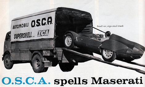
The Fratelli Maserati sold their name but kept their talent
by Karl Ludvigsen photos by the author.
IF THE AUTOMOTIVE WORLD can be said to have a fleeting, elusive Flying Dutchman, it must surely be the desmodromic Osca engine. Ever since late 1956, when the Maserati brothers declared that they had dispensed with springs, manifestations of the new engine have been reported from Sebring to Rouen, the most insistent stories usually being filed by those who've just been trounced by the suspect car. The document appearances are relatively few in number. First was September of 1957 at a Silverstone meeting, fitted to a Formula II chassis which was end-over-ended in its heat. Not damaged, the desmo engine was transplanted to a sports framework and raced at Spa shortly thereafter.
Since these events the pressure of sports car production and the development of a Grand Turismo engine for Fiat had moved the brothers' mechanically-closed valves to the back bench, but the recent enthusiasm (and finance) of Alejandro and Isabelle de Tomaso has caused' em to be dusted off and bolted to an engine of new dimensions mounted in an automobile rife with features new to the Osca organization. The resulting car is an intriguing pot-pourri of the classical and scientific approaches to sports car design.
It's logical that the Maserati brothers should have been the first to follow Mercedes' lead and produce a practical modern mechanical system to replace the valve springs. As is well known, some very close clearances and precise adjustments are called for. These can either be designed in bt a concentrated engineering effort or individually built in by expert, painstaking hand fitting. Daimler-Benz naturally chose the former route, while the Officine Specializzate per la Costruzioni di Automobili, with its intimate, feudal assemblage of artisans, elected an emphasis on execution rather than design. It works, and well, but frankly hasn't been so successful exploited as was the case at Stuttgart. In view of the relative size of the coffers at Bologna it's most remarkable that the Italian interpretation was at all.
For maximum utility, the desmodromic gear was first designed into the head for the 1491 cc engine with its traditionally square 78 mm dimensions. With a probable eye on Porsche developments and on the current preoccupation of Lotus and Cooper with Grand Prix equipment, it was decided to fit this new car into Class G. The 1350 cc block, a steppingstone from the original 1100 cc Osca to the Class F size, was pressed back into service to provide a diminished bore diameter which in connection with a much shorter stroke, reduced capacity to about 1090 cc. The exact dimensions haven't been released. Topping it off is the full 1500 cc cylinder head, with appropriate valve, port and carburetor sizes. It should provide altogether exceptional breathing at the expense of a complete engine on the heavy side for an 1100. You'll recall that Osca's most successful Class G contender to date was a 950 cc expansion of their very light 750 cc engine. The new car thus represents a full-circle turn in policy.
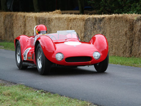
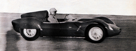 Alejandro de Tomaso puts the petite 1100 through its paces at the Modena Autodromo.
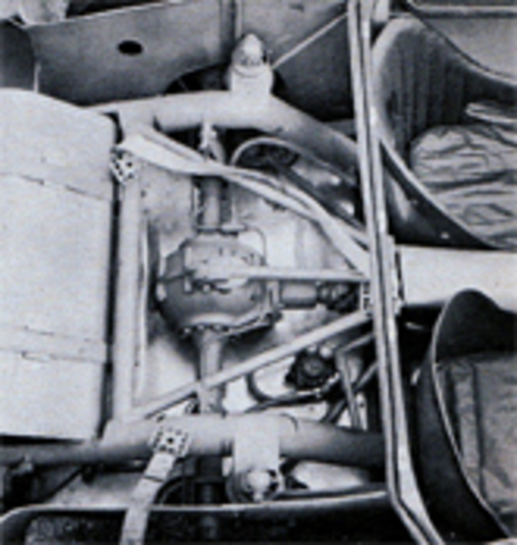
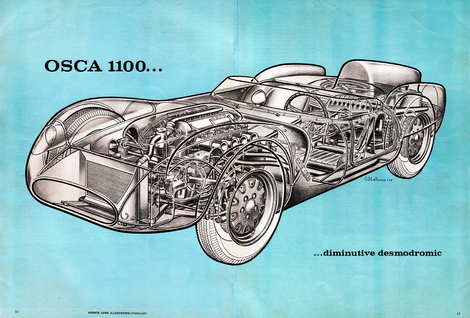 cutaway of the OSCA 1100 - the frame here is starting to resemble the delicate space frame of the famous birdcage.
All the products of the Maserati brothers have been characterized by simple, reliable design and construction methods well suited to the needs of the private owner - a tradition that began with their 1929 car, the first in European racing to have a detachable cylinder head. The light alloy block casting of their Osca of thirty years later is competently simple, its smooth flanks broken only by screw-in core plugs on the right and by water and breather connections on the left. A flanged wet steel-liner cylinder construction is used.
Ending conventionally at the crankshaft center line, the bottom of the block comprises the upper half of the crankcase and carries webbing to support the five plain main bearings. Main caps are amply dimensioned and retained by two studs each. All Oscas for sale have plain bearings throughout the bottom end, but further refinement has been carried out in this semi-factory machine. The rods have one-piece bottoms ends for use with roller big-end bearings, fitting of the rods and bearings being allowed by an assembled five-piece crankshaft. No complex Hirth system for the Bologna boys. They just carve octagonal extensions on the rod journals which mate very tightly indeed with similar holes in the corresponding cheeks. The union is consummated by freezing the journals and heating the cheeks, then assembling with the rods and rollers in place. Such an arrangement depends entirely on skilled hand work both to machine the mating surfaces and to align the assembled crank properly. Understandably, such cranks won't soon be turned over to private owners.
A combination of plain main bearings with roller rod bearings is sensible from several standpoints. For one, it allows the use of low-friction crank/rods assembly in an unchanged conventional block. Since the supply of lubricating oil is invariably to the rods by way of the mains, this arrangement also facilitates an internal flow of oil to the rod rollers without the (admittedly effective) expedient of slinger rings. Roller mains and plain rod shells would of course be impractical from the lubrication standpoint.
Extraordinary in these days of oil/water heat exchanges, big oil reservoirs and multiple-scavenge pump dry sump systems, this petite Osca has a plain old non-cooled wet sump lubrication layout. A wide deep cast alloy oil pan flares out away from the crankcase bottom face to give as much finned cooling area on the bottom as possible and also to hold as much oil as the proximity of the frame members will allow. A wire dipstick is inserted at the forward right-hand side, just aft of the single pressure oil pump. Bolted to the front of the timing chest right next to the oil pump, a small housing contains pressure-release and bypass valving and provides a mounting cap and stud for the angled replaceable-element oil filter.
Small pressure oil fittings are supplied on the sides of the block adjacent to the main bearing between cylinders three and four. A small tube from each carries oil to the center outside of each cam-box, from whence a gallery bathes the cam bearings and valve gear. Pressure is led to the dashboard gauge from a tee in the right-hand line. These very small pipes are the only external ducts in a very simple and hence reliable oil system. The use of a wet sump, with its limited capacity, also reflects Osca's confidence in the oil-retaining ability of the design and assembly of their engine. Since their units have an absolute minimum of external joints and usually finish races as spotlessly as they start, it seems justified.
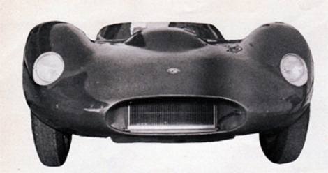 Radiator opening is efficiently small, fully ducted.
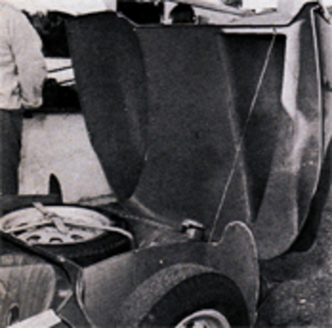 Upper tail section pivots for access to spare and gas tank. Wire strand limits its movement. Roll bars, like disc brakes, haven't caught on yet.
Now to the heart of this matter: the valve gear. Twin overhead camshafts are turned by a short set of three gears in the head hhich are powered by a roller chain from the crankshaft nose. Each cam is directly carried directly in the cylinder head casting by three plain bearings, their caps being retained by four studs each. Plenty of room is left in the widened camboxes for a desmodromic gear that closely resembles the Mercedes system (SCI, May 1957) in general layout.
Each valve is controlled by two cam lobes - one opening and one closing. Let's take the opening arrangement first. A conventional cam lobe is placed right over the end of the valve stem end, and pushes the valve open by contracting a very small mushroom-type "tappet" which is screwed onto the end of the short-stemmed valve. To be precise the stem screws into a tapped hole in the shank to engage a keyway-like slot along the valve stem. The threads being very fine, they assist in obtaining proper opening valve clearance.
Free to slid up and down along the tappet shank is a short tube with a flange at tis upper end, and between this flange and the underside of the mushroom top a very short, stiff coil spring is compressed. Backtracking a bit, a small-diameter shaft runs the length of each cambox along the inner or spark plug side. From this shaft is pivoted a closing bell crank for each valve. One ebd of the crank reaches out and encircles, with an oval aperture, the sliding collar and flange on the tappet shank. Offset to the left or right, depending on the valve, the other bell crank end is forked to accept a needle-mounted roller which rides against a large-diameter Mercedes-style closing cam lobe. Going the other direction, the closing cam presses against the bell crank roller, causing the other end of the crank to lift up against the sliding flange and thus, through the short spring, against the underside of the tappet screwed to the valve stem. The adjacent opening and closing cam lobes are naturally contoured so that each complements the motion of the other, one backing off while the other rises, and visa-verse.
As mentioned, all the valve closing cranks are pivoted from a common shaft for each cam, there being no neat independent adjustment for the pivot location of each crank as was the case in the Mercedes interpretation. This lack of a precise setting for total running clearance made the small springs along the stem necessary to ensure full seating of the valve. Keep in mind that these tiny springs do not actually themselves close the valves; they only keep the bell crank roller in constant and firm contact with the closing cam. Mercedes tried such springs in their valve gear at first but found them superfluous, thanks to the refinement of their adjusting system.
A detail worth mentioning is the application of pressure oil to the bell crank pivot shaft and finally to the opening cam and tappet by way of a spray hole in the bell crank. Although development is now at a relative standstill on this desmo gear, several details indicate the highly experimental nature of this head. The right-hand cam cover, for example, has a flange cast at its back end to accommodate a magneto or distributor if necessary (The left-hand cam turns the tach cable). Just above the ports along the sides of the head are two-bolt access plates of the type usually employed by Osca to support pivots for finger-type valve followers - possible remnants of an earlier desmodromic try, or a pessimistic means of utilizing the casting if the mechanical closure failed to function. Eight core plugs down the center of the head are an index to the complexity of the casting job, which included the provision of bosses for sixteen potential water offtake (or inlet) pipes, and wells for eight vertically-placed plugs for four cylinders.
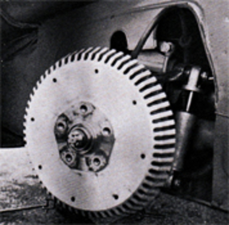 Big, solid looking drums are vented only for lining dust, water. Fully machined fins care for cooling. Wheels attach with bolts, not studs.
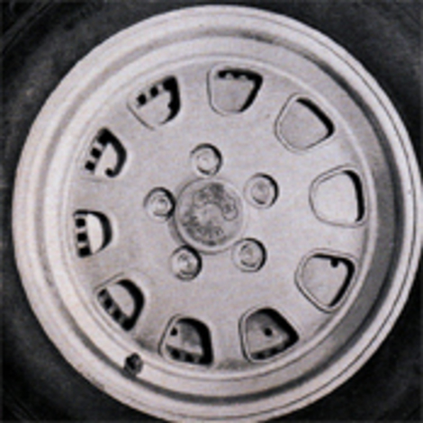 Copper-aluminum alloy wheels made by Amadori have deep T-section spokes for rigidity. Valve stem is metal, retained by nut to avoid shearing off.
Within the framework of the Osca engine, experience at Bologna has been that desmo gear greatly extends the maximum rev figure but has little effect on maximum power or the point at which it is reached. Were it to be applied in connection with direct injection and exceptionally high compression, as at Stuttgart, the results would have been different. As it stands it is certainly comforting to know that you are unlikely to bend a valve no matter how oblivious you are to the pleadings of the rev counter.
A Marelli twin-coil distributor juts forward from the front of the cylinder head, where it is driven by the central cam train gear. Wires to the plugs are liberal in length and bound together at several points, while the coils are placed far away on the left side of the firewall. None of these latter features are known to favor trouble-free ignition, and it may not be coincidence that in trials the usable revs of this 1100 cc engine have been limited to about 7500 by erratic firing. Lodge plugs are used.
Conventional in most respects, the water cooling system is centered around a low-placed FIM radiator, made in Bologna. For the first time a sports Osca has a small separate canister in the hot water return line as a location for the pressurized filler cap. The eight off-take pipes on the intake side of the head are utilized, as is the back one on the exhaust side. Two small vee-belts from a crank pulley drive a generator slung along the left side of the engine, a shaft from the back of the generator being coupled to a water pump at the center of the block. Its output is fed directly into the block at two points, adjacent to four crankcase breather outlets which are manifold into two big plastic vent pipes.
Contrasting with most competition layouts, this water pump location delivers cool water to the already cool intake side of the block and head. It wasn't always so, however. Until the 1957 season Oscas customarily had carburetors on the right and exhaust systems along the left-hand side, a configuration still used on the 750 cc cars. Before 1958 the works 1500 cc cars, perhaps for driver comfort, had the situation reversed, simplifying card linkages as well. Since only the porting and valving were changed, all the auxiliary connections were in effect reversed.
In its final developments stage the desmodromic 1500 Osca moved up from 40 mm Weber carbs to the more sophisticated 42 mm size, one of the largest ever to be applied to a 1500. When the head was bolted onto this 1100 the same carbs were retained, certainly setting a record for Class G fours. Of course they're choked well down - to 34 mm - but the potential is there. An electric fuel pump back by the riveted tank supplies a small frame-mounted fuel filter up front and then the two Webers through flexible hose and a tee fitting. The joints between carbs and head have limited flexibility, the carb weight being borne by three straps from the cam cover retaining cap-screws. A modern scavenging layout is used for the exhaust piping, the last two pipes meeting in customary pseudo-muffler and then reappearing to end just ahead of the rear tire. Below the exhaust ports, cradled between the flared oil pan and a tubular side egine mount, is found the lightweight starter motor with its pull-wire actuation.
Non webbed and fully enclosed, a two-piece bell housing shrouds the mechanically-actuated single-plate clutch and unites power production with torque multiplication. Newly for Osca the long, but slim, gearbox contains five forward gear choices and has what was described to us as "motorcycle-type" gear engagement. Presumably they have abandoned the synchro previously used on third and fourth cogs and have reinstated a simple, rugged dog-clutch system for the top four ratios at least. In conjunction with small, light gears this can produce extremely rapid shifts, often faster than are possible with a baulking type of synchromesh. Gear changes, to the ear anyway, are indeed completed instantly.
 Rigid rear axle rides on concentric coil-shock units, carefully located by two diagonal arms below, central arms above. Canvas straps limit rebound.
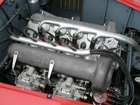
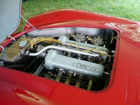
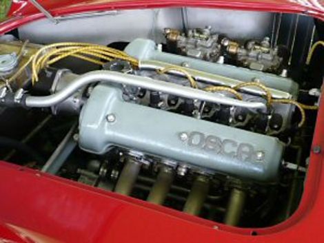
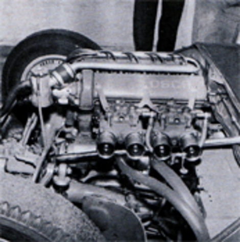 Large Webers dwarf the twin-cam four-cylinder engine. Braced by straps to cam cover, under which hides the desmodromic valves, they carry ram tubes and extensions to auxiliary venturi. Plastic hoses serve as breather pipes.
At the gearbox tail-shaft, just below the handy shift lever extension, nestles an external-contracting band handbrake controlled by a non-locking lever on the right. Strictly for downhill starting grids like Spa. Hooke-type joints and a large-diameter tubular prop shaft link up to the rear axle, which like late Ferrari productions betrays a garish practicality: live! Oscas have used both spiral and straight bevel gearing in their split alloy center sections, but since, as indicated by a neatly stamped tag, this one carries a tooth combination of 9 x 38 we can assume that they're the straight teeth giving a 4.22 ratio as used in the 1500's. Employment of the big axle also ties in with the generally heavy-duty bottom end and drive line of this muscular 1100. A ZF cam-type differential is also aboard.
Live-axle conservation is reflected in a simple twin-tube frame which says, "So I don't look like an engineering textbook. I won't break!" And it won't. Incessant Osca successes in the chassis-breakers like the Mille Miglia and Targa Florio have signed and sealed that. I this case the two main members are round steel tubes about three inches in diameter, formed primarily by cutting and welding straight sections together. They begin at the front with two complex fabricated curved pillars for the suspension members, joined by a large tube low down and a smaller one at the top. They spread apart through the firewall and reach maximum separation at the seats, there being a two-inch cross-member under the driver's thighs which supports the back of the gearbox and unites a pattern of angled and longitudinal central-bracing two-inch tubes. A main three-inch crossmember behind the seats ends the primary frame and forms a jumping-off place for rear suspension links and for the big tubes that arch up over the axle and are spilt into D-section members to support the riveted fuel tank and the battery.
As classic as the frame is the unequal-length wishbone front suspension. Accepting all the reactions of bucketed coil springs, shocks and anti-roll bar, the bottom arms are wide-based U-section forgings riding in metallic bushes for rigid location. I contrast the short top arms are profoundly daring by any standards, being machined out of aluminum blanks. They weigh a willowy 10.6 ounces apiece! The Maserati bothers also make their own tubular dampers, these very workmanlike units having two needle valve adjustments for internal fluid flow. They are not exceptionally well mounted, through the shock travel being only about half that of the wheel for a given deflection - a disproportion which decreases the damper's effectiveness. Related criticism applies to the high-mounted anti-roll bar, which like the upper frame crossmember is dipped at tis center to circumvent the distributor.
Conventional steering knuckles embrace short king pins, below which are bolted the forward facing steering arms. Simply, though not necessarily geometrically, these are joined by a two-piece track rod, the break occurring adjacent to the left-hand steering gearbox. Bolted into a fabricated niche in the frame and a considerable piece of machinery in its own right, this worm-based box actuates a forward-facing pitman arm and takes commands from a chrome-plated steering column.
Good results with a distinctive layout are obtained by the Osca location system for the light rear axle. Basic guidance is supplied by two fabricated box-section trailing arms which pivot at downward extensions from the steel axle housings. To provide lateral rigidity these arms are each braced to the frame crossmember by a small tubular strut with an angled rubber-bushed pivot at each end. An examination of this whole system will show that for one wheel to lift or for the car to roll the various rubber bushings in the members will be heavily stressed, imparting a degree of roll resistance but more importantly ensuring even firmer wheel control under such conditions. Putting it another way, if slop-free bushings replaced the rubber goods - the back end of this car could not roll at all.
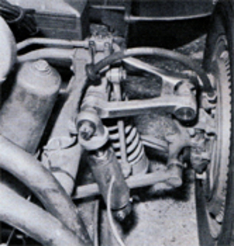 Upper wishbone is highly polished aluminum. Fully machined, it weighs but 10.6 ounces! Location of spring, shock seems dictated more by expediency than engineering principles.
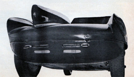 Lower tail section is vented to release heated air. Grenade-like hinge pins permit quick removal of upper portion.
A parallelogram to resist drive and braking torques is completed by a single trailing arm from the top of the driveshaft tunnel to a pivot atop the differential casing. Based on a one-inch tube, the arm has deeply gusseted end fittings. Perfectly vertical coil springs surrounding Osca tubular shocks are hung outboard of the frame kickups and apply their forces to the boxed trailing arms just forward of the axle. Each bottom spring cup is lightness-drilled and pivoted to itd trailing arm. Axle trvel is limited by canvas loops and rubber bump stops.
Brake mechanisms front and rear follow Maserati brothers' tradition in being of the conventional leading-trailing shoe type. the sturdy cast backing plates have but a small screened air scoop and no air outlet, and are recessed well into the wheels to boot. Heat dissipation should however, be well handled by massive new cross-finned brake drums which boast a large volume of aluminum bonded around their ferrous liners. Drum internal diameters are ten inches in front and nine in the rear. A pushrod and bell crank linkage from the pedal actuates the single master cylinder, placed in a decided hot spot between the left-hand frame member and the engine oil pan. An indicating-plunger fluid reservior is mounted on the firewall.
Frequently seen on new Oscas of all sizes is a neat ten-spoke disc wheel, designed by Ernesto Maserati and made by the up-and-coming Amadori firm right next door to Osca on the Via Emilia. A coat of aluminum paint on each wheel conceals a color which indicates a high percentages of copper in the light alloy. Each spoke is backed up by a radial stiffening rib, giving them a T-section. The wheels are concentrically located by close-fitting raised spigots on the brake drums, and clamped on by five cap screws with relieved heads. This attachment system is adequate for medium-length events with the excellent tire life noow available, but a wheel change would be a double bother as these cap screws appear to require additional tightening to ensure solid mounting after the brake drums have been warmed up. Perhaps this would not be so critical if the cap screws were relieved of braking and drive torques. Wheels and tires are 15 inch, the front rim and tire sizes being 3.5 and 5.00 respectively, with 4 and 5.25 in use at the rear.
Still built by Morelli in Ferrara, the body is a considerable departure from past Osca patterns in both shape and construction. In the former respect it blends a Lister-like nose and a lumpy hood with a high, full windshield and a squared, sharply carved tail that partially encloses the rear wheels. Regarding the latter it features a nose and tail that hinge up and away from the center of the car to expose chassis and drive components beautifully. Leather straps retain these covers, which have more of an impression of flimsiness than is usual with the tube-framed Morelli body construction.
Seen overall this is truly an Osca "special", assembled from a variety of new and old ideas around the shop for the particular benefit of de Tomaso. It envelops their classic Italian chassis with an admittedly Britanic body shell and powers it with a potentially devastating 1100 cc engine. It's new to Osca and will take some sorting out, but if that can be accomplished within reasonable time it'll be very hard to catch. Even better it may point a new line of endeavor for the patient brothers Maserati.
*- Karl Ludvigsen*
Other images of OSCA cars of the 50's to '61
A brief history of owners of the company:
The Maserati brothers, Alfieri, Bindo, Carlo, Ettore, Ernesto and Mario, were all involved with automobiles from the beginning of the 20th century. Alfieri, Bindo and Ernesto built 2-litre Grand Prix cars for Diatto. In 1926, Diatto suspended the production of race cars, leading to the creation of the first Maserati and the founding of the Maserati marque. One of the first Maseratis, driven by Alfieri, won the 1926 Targa Florio. Maserati began making race cars with 4, 6, 8 and 16 cylinders (actually two straight eights mounted parallel to one another). Mario, an artist, is believed to have devised the company's trident emblem, based on one the Fontana del Nettuno, Bologna. Alfieri Maserati died in 1932 but three other brothers, Bindo, Ernesto and Ettore, kept the firm going, building cars that won races.
Orsi ownership In 1937, the remaining Maserati brothers sold their shares in the company to the Adolfo Orsi family, who in 1940 relocated the company headquarters to their hometown of Modena, where it remains to this day. The brothers continued in engineering roles with the company. Racing successes continued, even against the giants of German racing, Auto Union and Mercedes. In 1939, a Maserati 8CTF won the Indianapolis 500, a feat repeated the following year.
The war then intervened, Maserati abandoning cars to produce components for the Italian war effort. During this time, Maserati worked in fierce competition to construct a V16 towncar for Benito Mussolini before Ferry Porsche of Volkswagen built one for Adolf Hitler. This failed, and the plans were scrapped. Once peace was restored, Maserati returned to making cars; the Maserati A6 series did well in the post-war racing scene. Key people joined the Maserati team. Alberto Massimino, an old Fiat engineer, with both Alfa Romeo and Ferrari experiences oversaw the design of all racing models for the next ten years. With him joined engineers Giulio Alfieri, Vittorio Bellentani, and Gioacchino Colombo. The focus was on the best engines and chassis to succeed in car racing. These new projects saw the last contributions of the Maserati brothers, who after their 10-year contract with Orsi expired went on to form O.S.C.A.. This new team at Maserati worked on several projects: the 4CLT, the A6 series, the 8CLT, and, pivotally for the future success of the company, the A6GCM.
The famous Argentinian driver Juan-Manuel Fangio raced for Maserati for a number of years in the 1950s, producing a number of stunning victories including winning the world championship in 1957 in the Maserati 250F alongside Toulo de Graffenried, Louis Chiron, Prince Bira, Enrico Platé, and a few others. Other racing projects in the 1950s were the 200S, 300S (with several famous pilots, among them Benoit Musy), 350S, and 450S, followed in 1961 by the famous Tipo 61.
Maserati had retired from factory racing participation due to the Guidizzolo accident in 1957, though they continued to build cars for privateers. After 1957, Maserati became more and more focussed on road cars, and chief engineer Giulio Alfieri built the 6-cylinder 3500 2+2 coupé, which featured an aluminum body over Carrozzeria Touring's superleggera structure, a design also used for the small-volume V8-powered 5000. Next came the Vignale-bodied Sebring, launched in 1962, the Mistrall Coupé in 1963 and Spider in 1964, both designed by Pietro Frua, and also in 1963, the company's first four-door, the Quattroporte, designed by Frua as well. The two-seat Ghibli coupé was launched in 1967, followed by a convertible in 1969.
Body style was embraced by many sports car manufactures of the time 40's and 50's occasionally revived today:
A barchetta—the word is Italian for "little boat"—was originally an Italian style of open 2-seater sports car that was built for racing. Weight and wind-resistance were kept to a minimum, and any unnecessary equipment or decoration was sacrificed to performance.
Although most barchettas were made from the late 1940s through the 1950s, the style has occasionally been revived by small-volume manufacturers and specialist builders in recent years.
Typically hand-made in aluminium on a tubular frame, the classic barchetta body is devoid of bumpers or weather equipment such as canvas top or sidescreens.
There is no provision for luggage. Some barchettas have no windscreen; others, a shallow racing-type screen or aero screen(s).
The classic barchetta either has no doors, in which case entry and egress is made by stepping over the side of the car, or very small doors without exterior handles.
Origin and examples
Giovanni Canestrini, when he was the editor of La Gazzetta dello Sport, a popular Italian sporting newspaper, was the first to bestow the sobriquet "barchetta" on a car, using it to describe the new Ferrari 166MM displayed at the 1948 Turin Auto Show. The name has been associated with this model ever since.
The MM in the car’s designation stood for Mille Miglia, the race it won in 1948 and 1949. In 1949 the 166MM barchetta also won the 24 Hours of Le Mans (driven by Luigi Chinetti and Lord Selsdon) and the Targa Florio (with Clemente Biondetti and Igor Troubetzkoy), the only car ever to win all three races in the same year. It also won the 1949 Spa 24 Hours. The car’s unadorned, lightweight aluminium body was designed by Carrozzeria Touring’s head of design, Carlo Felice Bianchi Anderloni. Motor Trend Classic rated the 166MM Barchetta sixth out of the ten "greatest Ferraris of all time".  
Barchetta-bodied OSCA MT4
The OSCA MT4, 1,452 cc, 130 bhp barchetta made by the Maserati brothers, was for eight years the most successful under-1500 cc sports racing car in the world. Other, even more diminutive OSCA Barchettas were powered by engines of 750 cc and 850 cc. Giovanni Moretti, another designer and manufacturer, also made several small barchettas in the 1950s. The 1966 Abarth 1000SP Barchetta was a successful race car, and in 2007 the car design firm Carrozzeria Bertone celebrated its 95th anniversary with the Fiat Panda-based Fiat Barchetta Bertone, an "open-topped strictly two-seater sports car that calls to mind the Italian racing cars of the 1950s. In this case, the design explicitly cites the Fiat 500 with Barchetta bodywork created by the young Nuccio Bertone in 1947 as a one-off for his personal use in races [...and] projects the concept of the Barchetta, a historic icon in the legend of Italian motorsports, into the future with purposeful elegance and sophisticated irony. 
Ferrari 550 Barchetta
Ferrari revived the name in 2001 for their 550 Pininfarina Barchetta, which marked Pininfarina’s 70th anniversary. The car was first shown at the 2001 Salon de l'Automobile and 448 examples were built. It is "[i]n many ways...the legitimate successor to such legendary open Ferraris as the 166MM..." Designed as a roadster for use on public roads and not as a full-blooded racing car, the 550 Barchetta has a rudimentary convertible top "whose mechanism is said to require strength, skill, and patience." The top is intended only for emergency use in a sudden downpour and the manufacturer advises against using it at speeds above 70 mph. The top "doesn't look as if it would survive the sacrilege of an automatic carwash." List price of the 550 Barchetta was $245,000.  
Barchetta-style Renault Spider
The 2000 Renault Spider, although mid-engined, was designed very much in the barchetta style; and also in the barchetta tradition, as it was intended for racing. Renault sponsored a one-make race series for it. Although the Spider is road-legal it has no weather protection, and drivers of first-series Spiders usually wear a helmet on the road as these early models were sold without the windscreen that came with the later models.
Major technical changes included the addition of the desmodromic valve system to the 1500 cc engine:
Ideal The common valve spring system is satisfactory for traditional mass-produced engines that do not rev highly and are of a design that requires low maintenance. At the period of initial desmo development, valve springs were a major limitation on engine performance because they would break from metal fatigue. Vacuum melt processes developed in the 1950s helped remove impurities in the steel used to make valve springs, although after sustained operation above 8000 RPM often springs would still fail. The desmodromic system was devised to remedy this problem. Furthermore, as maximum RPM increases, higher spring pressure is required to return the valve, leading to increased cam drag and higher wear on the parts at all speeds, problems addressed by the desmodromic mechanism.
Design and history Fully controlled valve movement was thought of in the earliest days of engine development, but devising a system that worked reliably and was not overly complex took a long time. Desmodromic valve systems are first mentioned in patents in 1896 by Gustav Mees, and in 1907 the Aries is described as having a V4 engine with "desmodromique" valve actuation, but details are scarce. The 1914 Grand Prix Delage used a desmodromic valve system (quite unlike the present day Ducati system). Azzariti, a short lived Italian manufacturer from 1933 to 1934, produced 173 cc and 348 cc twin cylinder engines, some of which had desmodromic valve gear, with the valve being closed by a separate camshaft. The Mercedes-Benz W196 Formula One racing car of 1954-55, and the Mercedes-Benz 300SLR sports racing car of 1955 all had desmodromic valve actuation. In 1956 Fabio Taglioni, a Ducati engineer, developed a desmodromic valve system for the Ducati 125 Grand Prix, creating the Ducati 125 Desmo. He was quoted to say… The specific purpose of the desmodromic system is to force the valves to comply with the timing diagram as consistently as possible. In this way, any lost energy is negligible, the performance curves are more uniform and dependability is better. The engineers that came after him continued that development, and Ducati holds a number of patents relating to desmodromics. Desmodromic valve actuation has been applied to top-of-the-range production Ducati motorcycles since 1968, with the introduction of the "widecase" Mark 3 single cylinders. In 1959, the Maserati brothers introduced one of their final designs: a desmodromic four cylinder, 2000cc engine for their last O.S.C.A. Barchetta. 
Benefits In modern engines, valve spring failure at high RPM has been mostly remedied. The main benefit of the desmodromic system is the prevention of valve float. In traditional spring valve actuation, as engine speed increases, the inertia of the valvetrain overcomes the spring's ability to close the valve completely before the piston reaches TDC (Top Dead Centre). This can lead to several problems. First, and most catastrophic, the piston will collide with the valve and thus damage both permanently. Second, the valve will not completely return to its seat before combustion begins. This allows cylinder gases and pressure to escape prematurely, which causes a major decrease in engine performance and can cause the valve to overheat, possibly causing warping or catastrophic valve failure or both. In valve spring engines the traditional remedy for valve float is to make the springs stronger (stiffer). This increases the seat pressure of the valve, which is the static pressure that holds the valve closed. This is of benefit at higher engine speeds by reducing the aforementioned valve float. The drawback is that to open the valve the engine has to work harder. The higher spring pressure causes greater pressure (hence temperature and wear) in the valve actuation mechanism. The desmodromic system avoids this problem, because although it has to work against the directional energy of the valve opening and closing, it does not have to overcome the static energy of the spring.
Disadvantages Before the days when valve drive dynamics could be analyzed by computer, desmodromic drive seemed to offer solutions for problems that were worsening with increasing engine speed. Famous examples of successful desmodromic engines were Mercedes-Benz W196 and Mercedes-Benz 300 SLR racing cars. Since those days, lift, velocity, acceleration, and jerk curves for cams have been modeled by computer to reveal that cam dynamics are not what they seemed. With proper analysis, valve adjustment, hydraulic tappets, push rods, rocker arms, and above all, valve float, became things of the past...without desmodromic drive. Today most automotive engines use overhead cams, driving a flat tappet to achieve the shortest, lightest weight, and most inelastic path from cam to valve, thereby avoiding elastic elements such as pushrod and rocker arm. Computers enabled accurately designing acceleration profiles, the most important dynamic of valve motion, because it defines forces from F=Ma (Force equals Mass times Acceleration). Before numerical computing methods were readily available, acceleration was only attainable by differentiating cam lift profiles twice, once for velocity and again for acceleration. This generates so much hash (noise) that the second derivative (acceleration) was uselessly inaccurate. Computers permitted integration from the jerk curve, the third derivative of lift, that is conveniently a series of contiguous straight lines whose vertices can be adjusted to give any desired lift profile. Integration of the jerk curve produces a smooth acceleration curve while the third integral gives an essentially ideal lift curve (cam profile). With such cams, that mostly do not look like the ones "artists" formerly designed, valve noise (lift-off) went away and valve train elasticity came under scrutiny. Today's cams have mirror image (symmetric) profiles with identical positive and negative acceleration while opening and closing valves. An asymmetric cam either opens or closes valves more slowly than it could, speed being limited by Hertzian contact stress between curved cam and flat tappet from accelerating the mass of valve, tappet and spring. In contrast, desmodromic drive uses two cams per valve, each with separate rocker arm (lever tappets). Maximum valve acceleration being limited by cam-to-tappet galling stress, is governed by moving mass and cam contact area. Rigidity and contact stress are best achieved with conventional flat tappets and springs whose lift and closure stress is unaffected by spring force, both occurring at the base circle where spring load is minimum and contact radius is largest. Curved (lever) tappets of desmodromic cams cause higher contact stress than flat tappets for the same lift profile, thereby limiting rate of lift and closure. With conventional cams, stress is highest at full lift, when turning at zero speed (engine cranking), and diminishes with increasing speed as inertial force of the valve counter spring pressure, while a desmodromic cam has essentially no load at zero speed (in the absence of springs), its load being entirely inertial, and therefore increasing with speed. However, its greatest inertial stress bears on its smallest radius. Acceleration forces for either method increase with the square of velocity resulting from kinetic energy. Desmodromic valve drive was often justified] by claims that springs could not close valves reliably at high speed and that the forces caused by suitably strong springs exceeded what cams could withstand. Since then[ valve float was analyzed and found to be caused largely by resonance in valve springs that generated oscillating compression waves among coils, much like a Slinky. High speed photography showed that at specific resonant speeds, valve springs were no longer making contact at one or both ends, leaving the valve floating [9] before crashing into the cam on closure. For this reason, today as many as three concentric valve springs are sometimes nested inside one other; not for more force (the inner ones having no significant spring constant), but to act as snubbers to reduce oscillations in the outer spring. An early solution[when?] to oscillating spring mass was the mousetrap or hairpin spring used on Norton Manx engines. These avoided resonance but were ungainly to locate inside cylinder heads. Today, formula-one racing engines use gas springs that have no resonant parts, their working parts having an insignificant mass compared to the force of their compressed gas. These springs are expensive and short lived, therefore, offering no benefit for most engines.[ Valve springs that do not resonate are progressive, wound with varying pitch or varying diameter called beehive springs from their shape. The number of active coils in these springs varies during the stroke, the more closely wound coils being on the static end, becoming inactive as the spring compresses or as in the beehive spring, where the small diameter coils at the top are stiffer. Both mechanisms reduce resonance because spring force and its moving mass vary with stroke. This advance in spring design removed valve float, the initial impetus for desmodromic valve drive. Overhead cams using flat tappets and springs offer advantages over desmodromic drive in current automotive engines]. Currently the only major manufacturer using desmodromic drive is Ducati, in motorcycle engines. Reasons for not using a desmodromic approach are increased maintenance and valve noise which can be uncomfortably loud in engines with four or more cylinders.
Controversy While the desmodromic system is not the most ideal in a practical world of mechanics, it still survives and performs without problem to this day. While it can be more expensive to maintain than traditional spring actuated valve systems, there are many aftermarket precision machined components which can extend the maintenance interval to that of the almost magical spring actuated systems (in comparable motorcycles). While newer, high performance, pneumatic systems may follow more specific design and engineering specifications (computer aided) they are typically limited to race only applications (Formula 1, Moto GP, etc). Currently, there is no method of determining longevity or extended maintenance intervals of such systems in practical, everyday, systems such as the automobile. While the design can be noisy, it is typically overridden by road noise from tires and other engine components such as intake and exhaust noise. Though stated above the noise is "uncomfortably loud in engines with four or more cylinders", if true, this is limited (in terms of Ducati) to the MotoGP and MotoGP Race Replica bikes which are the only current production desmodromic motors that feature four cylinders; they are intended for race use. (It should be noted that exhaust noise levels can exceed 110dB on full race systems.)
Posted 12/02/08 @ 05:30 PM | Tags: OSCA, OSCA 1100, Maserati, Fratelli Maserati, Sports Car Illustrated February 1959, Alejandro de Tomaso, Modena Autodromo, desmodromic, Weber carburetors, desmodromic valves, Ernesto Maserati, Morelli in Ferrara, Maserati brothers, Mille Miglia, Sports Car Graphic magazine